Engineering Authority: Architectural Glass Canopy Plans & Structural Design
The modern architectural canopy serves as a high-stakes threshold, bridging the climate-controlled interior with the chaotic variables of the exterior environment. While its primary function—providing shelter from precipitation and managing solar gain—remains utilitarian, the transition to glass as a primary medium has fundamentally altered the engineering profile of these structures. Architectural Glass Canopy Plans . A contemporary glass canopy is a sophisticated assembly that must reconcile the inherent transparency of its material with the brutal mechanical demands of wind uplift, seismic shifting, and heavy snow accumulation.
Developing professional architectural glass canopy plans requires a multidisciplinary approach that effectively merges aesthetic ambition with a “failure-first” engineering mindset. When glass is moved from a vertical wall to an overhead position, the physics of safety shifts. Gravity becomes the primary antagonist, necessitating a deep exploration of post-breakage behavior and lamination technologies. The objective is to ensure the canopy remains a protective asset rather than a overhead liability in the event of a structural compromise.
Navigating the technical specifications within these plans involves more than just calculating glass thickness. It requires an interrogation of the connection points—whether they are point-supported spider fittings, continuous compression channels, or tension-rod assemblies—and how these hardware choices distribute stress across the glass substrate. This analysis serves as a definitive exploration of the technical frameworks, risk variables, and planning dynamics essential for mastering the design and implementation of professional-grade glass canopy systems.
architectural glass canopy plans
To evaluate architectural glass canopy plans with editorial rigor, one must view the document as a comprehensive roadmap for managing energy transfer. This includes the mechanical energy of environmental loads and the thermal energy of solar radiation. A frequent misunderstanding in the field is the assumption that “safety glass” is a generic, monolithic category. In the context of overhead plans, safety glass is highly specific, almost always requiring heat-strengthened laminated glass that has been rigorously tested for edge-retention and interlayer stability.
The complexity of these plans often resides in the “unseen” variables. This includes expansion joints designed to prevent the glass from crushing itself during an extreme heatwave, or the precise pitch calculations required to ensure water does not “pond” in the center of a pane. Ponding is particularly dangerous; it leads to structural deflection that can eventually exceed the capacity of the sealants. An oversimplified plan might focus on the visual transparency while neglecting the chemical compatibility between the laminated interlayer and the edge sealants. If these materials react, delamination occurs, resulting in a clouded, structurally compromised perimeter.
Topical mastery in this domain requires a shift from seeing the canopy as a “product” to seeing it as a “dynamic structural assembly.” This means the architectural glass canopy plans must define a clear, redundant load path. The forces must move from the glass surface, through the fittings, and into the building’s primary skeleton, all while accounting for the inevitable tolerances and movements of on-site construction.
Evolution of Overhead Glazing Systems
The use of overhead glass dates back to the 19th-century iron-and-glass palm houses, yet those structures relied on small, overlapping panes that functioned similarly to shingles. The modern “seamless” glass canopy is a product of the late 20th-century revolution in structural glazing. The catalyst was the development of the “spider” fitting—an articulated stainless steel arm that allowed glass to be held at its corners, facilitating massive expanses of transparency without bulky metal rafters.
This evolution has been mirrored by advances in interlayer chemistry. Traditional PVB (polyvinyl butyral) interlayers are excellent for impact but remain relatively soft. The introduction of ionoplast interlayers (such as SentryGlas) provided the requisite stiffness for “structural” glass, where the glass actually contributes to its own support. We have moved from a philosophy of “containing” glass within heavy frames to “liberating” it through point-fixings, a transition that has placed a much higher burden of accuracy on the initial planning stages.
Conceptual Frameworks and Mental Models
When analyzing a canopy plan, professionals employ specific mental models to filter complex data:
-
The Redundancy Ratio: This framework asks: “If one connection point fails, or one lite of a laminate shatters, does the system have a secondary path to prevent total collapse?” High-performance plans prioritize “fall-safe” over “break-safe.”
-
The “Dead vs. Live” Equilibrium: This model separates the constant weight of the glass (dead load) from transient forces like snow or wind (live loads). A plan is only as robust as its ability to handle the “worst-case” live load without permanent deformation of the hardware.
-
The Thermal Movement Arc: Glass and steel expand at different rates. This model views the canopy as a “breathing” structure, ensuring the plan includes enough “slip” in the fittings to accommodate seasonal temperature swings without creating localized stress concentrations.
Structural Categories and Mechanical Variations
Structural strategies generally fall into five categories, each with distinct trade-offs regarding cost, weight, and visual impact.
1. Point-Supported (Spider) Systems
Utilize articulated bolts that pass through drilled holes in the glass. This offers maximum transparency but requires highly precise glass fabrication. If the holes are off by even 2mm, the entire pane may be unmountable.
2. Cantilevered Glass
The glass is “clamped” at one end and extends into space without external support. This creates a striking “floating” effect but places immense stress on the base channel and requires significantly thicker glass to manage the leverage of the cantilever.
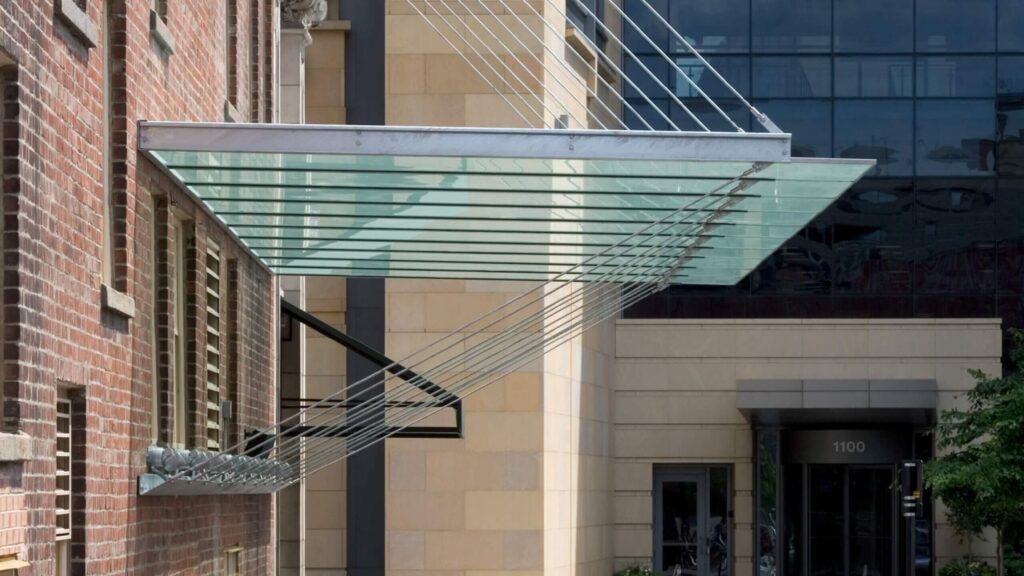
3. Tension Rod and Mast Systems
The glass is supported by thin cables or rods from above. This is ideal for large-scale entranceways where a heavy frame would be unsightly. The primary trade-off is the need for high-tension anchor points on the building facade.
Comparison Table: Structural Dynamics
| Feature | Point-Supported | Cantilevered | Tension Rod | Framed |
| Visual Weight | Low | Ultra-Low | Medium | High |
| Glass Thickness | High (Laminated) | Very High | Moderate | Low |
| Tolerance Sensitivity | Critical | High | Moderate | Low |
| Cost Profile | Premium | High | Moderate | Standard |
Detailed Real-World Scenarios Architectural Glass Canopy Plans
Scenario A: The “Snow Dump” Region
In climates like the Pacific Northwest, the canopy must account for “unbalanced snow loads”—where snow accumulates more heavily on one side due to wind patterns. A plan that only accounts for uniform weight will fail here. The solution is often a sloped profile (at least 5 degrees) to encourage shedding and a heat-soaked glass treatment to handle the cold-stress.
Scenario B: High-Traffic Retail Entrances
Safety is the primary driver here. The plan must specify a “sacrificial” lite—a laminated assembly where even if the bottom layer is smashed by a vandal, the top layer and the interlayer have the “stiffness” to keep the panel from sagging until it can be replaced. Failure to specify a structural interlayer in this scenario creates a significant liability.
Planning, Cost, and Resource Dynamics
The economic reality of a glass canopy is often dictated by the “complexity of the connection.” Custom-machined stainless steel fittings can easily double the cost of the glass itself. Furthermore, the “logistic cost” of installing oversized glass panes—requiring specialized vacuum lifters and potentially street closures—must be accounted for in the resource plan.
| Resource Category | Direct Cost Impact | Variability Factor |
| Glass Fabrication | Moderate | Coating (Low-E / Frit) |
| Structural Steel/Fittings | High | Custom vs. Off-the-shelf |
| Engineering Seals | Low | Seismic/Wind Zone complexity |
| Installation Labor | High | Site access and height |
Risk Landscape and Failure Modes
The primary failure mode in glass canopies is edge delamination. This occurs when water is allowed to sit against the laminated edge, eventually “wicking” into the interlayer and causing the glass to separate.
Another critical risk is impact-induced fracture. While tempered glass is strong, it is vulnerable to “point-impacts” on its edges. A plan that leaves glass edges exposed in a high-traffic area (where they might be hit by a delivery truck or a swinging ladder) is a plan prone to failure. Protective edge-caps or recessed channels are common mitigations that must be designed into the initial drawings.
Governance, Maintenance, and Long-Term Adaptation
A canopy should be treated as a monitored asset. Maintenance is not just about cleaning; it is about structural verification.
Layered Maintenance Checklist:
-
Gasket Inspection: Are the EPDM or silicone gaskets still flexible, or have they “shrunk” and created gaps?
-
Bolt Tensioning: On point-supported systems, have the vibrations of the building or wind loosened the cap-bolts?
-
Drainage Paths: Are the gutters or “weep holes” clear of organic debris that could cause water to back up into the structural channels?
Measurement, Tracking, and Evaluation
Evaluating the success of a canopy installation involves both quantitative and qualitative signals:
-
Leading Indicators: Deflection measurements during initial load testing (comparing the “as-built” dip to the “as-modeled” dip under load).
-
Lagging Indicators: Evidence of “discoloration” at the laminate edges after the first five years, indicating a failure in the moisture barrier.
-
Documentation Example: A “Glass Registry” should be maintained, noting the exact dimensions, heat-soak batch number, and coating type for every pane, ensuring that if one breaks in ten years, a perfect match can be ordered without re-measuring the entire structure.
Common Misconceptions
-
“Glass is a perfect insulator.” Overhead glass can create a “heat trap” underneath if not treated with a ceramic frit (dots) or a solar-control coating.
-
“Laminated glass is unbreakable.” Laminated glass is designed to stay together when broken, not to resist all forms of breakage.
-
“The building’s wall can always take the load.” A canopy acts as a massive lever. Without “backing” plates or structural reinforcement inside the wall, the canopy can literally pull the bricks or siding off a building.
Conclusion
The execution of architectural glass canopy plans represents a convergence of high-stakes engineering and aesthetic ambition. As urban density increases and we seek to maximize the utility of outdoor spaces, the canopy will continue to evolve toward smarter, lighter, and more resilient forms. Success in this field requires the intellectual honesty to admit that glass is a material of “controlled vulnerability.” By planning for its specific failure modes and respecting the physics of transparency, we can create structures that are as durable as they are beautiful. The final measure of a canopy is not found in the day it is installed, but in its ability to remain clear, stable, and safe decades after the scaffolding has come down.